.
LM1040 tone control circuit design electronic project
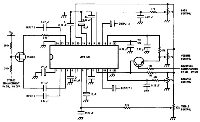
A very simple tone control circuit project can be constructed using this electronic schematic circuit diagram that is based on the LM1040 tone control IC .
When adjusted for maximum boost in the usual application circuit, the LM1040 cannot give additional boost from the loudness control with reducing gain. If it is required, some additional boost can be obtained by restricting the tone control range and modifying Ct, Cb, to compensate.
The typical DC level at pins 3 and 22 is 7.5 V (Vcc= 12V), with the input signal superimposed, and this can be used to bias a FET switch as shown to save components. For switching with a 0V-5V signal a low-threshhold FET is required when using a 12V supply. With larger switching levels this is less critical.
The high impedance PNP base input of the loudness control pin 9 is readily switched with a general purpose NPN transistor.
As you can see in the circuit diagram , this electronic schematic has two separate inputs and two outputs and one stereo enhancement switch connection .

- Log in to post comments


