.
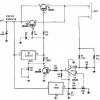
Cell phone charger circuit diagram FSEZ1307
This cell phone charger circuit diagram electronic project is based on the FSEZ1307 third-generation primary side regulation (PSR) PWM controller integrated circuit .
The FEZ1307 cell phone charger can be used for battery chargers applications for devices like : cellular phones, cordless phones, PDA, digital cameras or for replacement of linear transformers and RCC SMPS .
The FEZ1307 is designed to work using few external components offering many other features like : low standby power: under 30mW, high-voltage startup, constant-voltage (CV) and constant-current (CC) control without secondary-feedback circuitry , fixed PWM frequency at 50kHz with frequency hopping to solve EMI problem , cable compensation in CV mode , peak-current-mode control in CV mode , cycle-by-cycle current limiting , VDD over-voltage protection with auto restart , VDD under-voltage vockout (UVLO) , gate output maximum voltage clamped at 15V , fixed over-temperature protection with auto restart .
This cellular phone charger accepts a wide range input voltage from 90 to 265V AC and provide a 5 volts DC at 0.7 A .

- Log in to post comments


