.
ULN2004 water level indicator circuit


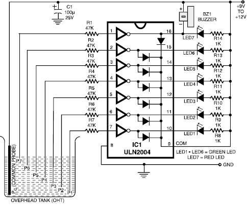
This ULN2004 electronic project circuit diagram design is a very simple water level indicator circuit project . This ULN2004 water level indicator circuit is very simple and require few external electronic parts .
ULN2004 is a high voltage, high current darlington arrays that contain seven open collector darlington pairs with common emitters . Each channel rated at 500mA and can withstand peak currents of 600mA.
As the water level rise in the tank , it comes in contact with probes P1 through P7 and thereby makes pins 7 trough 1 high sequentially . The corresponding output pins 10 trough 16 go low one after other and LED1 through LED7 will light up . When water comes in contact with the last probe P7 , the buzzer connected to the last pin 16 will sound .
This electronic circuit project must be powered from a fixed output DC voltage that will provide an output voltage between 9 and 12 volts .
- Log in to post comments
Comments
Regarding the type of buzzer being used
you can use a 12 VDC piezo
Reliability
What If I give 12V 1A Power supply
LED doesnt hold well with 12v