.
LM350 Car battery charger circuit design


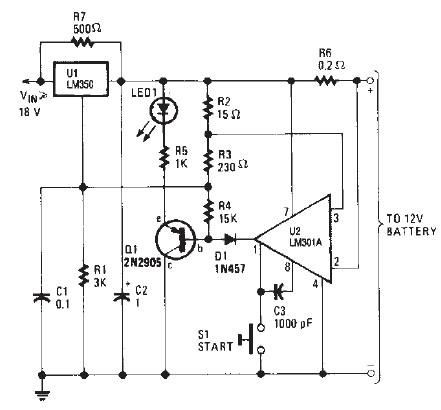
This LM350 Car battery charger circuit project is a high performance charger that quickly charges gelled lead-acid batteries and turns off the charger process at full charge . This LM350 Car battery charger circuit will provide a charge current of 2A when the battery is nod fully charged , but as buttery voltage rise , current decreases .
When the current falls to 150 mA , the charger automatically switches to a lower float voltage to prevent the overcharging . When the charging process is finish the transistor Q1 make the LED1 to glow , to indicate the state of charging process . The small value resistors R2, R3 , R6 must be 1 watt resistors and R7 must be 5 watts resistors.
When the push button switch is pushed , the output voltage of the charger goes to 14.5 V and when the battery approaches to full charge, the charging current decreases and the output voltage is reduced to about 12.5 V .
The input voltage for this battery charger electronic circuit must be around 18 volts DC .
- Log in to post comments