.
Amplifier power supply electronic circuit project design


A very simple amplifier power supply that can be used in many power audio amplifier circuits where is needed an very good filtered and high efficiency power supply is presented in this electronic project . This amplifier power supply electronic project circuit diagram presented here describes how to design a power supply circuit using few common electronic parts.
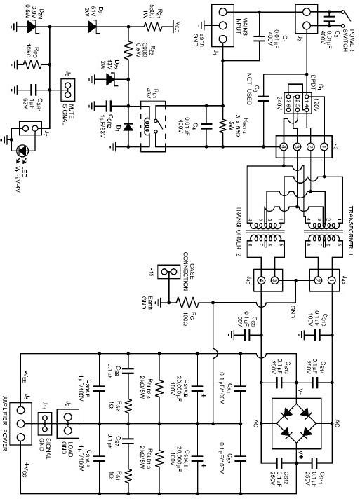
The design uses toroidal transformers, a fully integrated bridge, and various rail capacitors for ripple voltage reduction, noise suppression, and to act as high current reservoirs. Also additional circuitry to control inrush current on power up and power up down Mute control are also included.
C1, C2, C4 capacitors are used to protect against turn on/off spikes caused when the power switch changes positions. C3 is not used and is redundant.
CS1, CS2 capacitors are low value, ceramic capacitors to filter higher frequency noise right at the DC output of the diode bridge.
CS3, CS4 are the large reservoir capacitors to supply large current demands and stabilize the supply rails to minimize low frequency fluctuations.
CS5, CS6 are high quality film capacitors to filter higher frequency noise.
CS7, CS8 capacitors act in conjunction with RS1 and RS2 to decouple the large electrolytic capacitors and reduce impedance.
CS9, CS10 are low value, ceramic capacitors to filter higher frequency noise from the transformer secondary AC lines at the diode bridge.
CS11 - CS14 capacitors are in parallel with the bridge diodes to reduce high frequency noise and ringing of the diode. An additional RC snubber in parallel with each diode of the rectifier will further reduce noise and ringing.
- Log in to post comments